
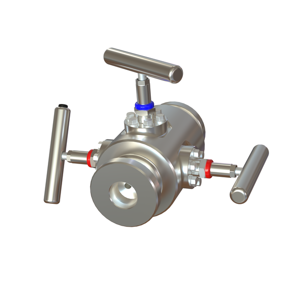
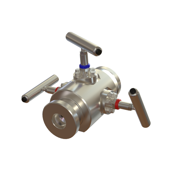
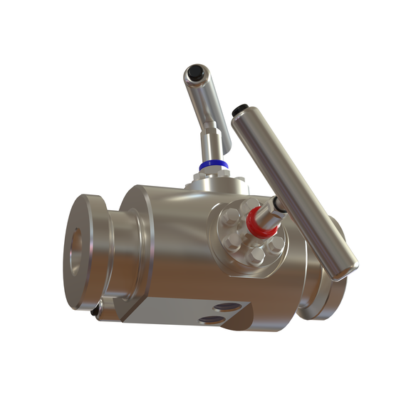


Chemical Injection Valve w/ Double Hub
Specifications
| Article number | Size | Ventilate | Tmin. | Tmax. | Material | Inlet & Outlet | Orifice size | Purge Port |
|---|---|---|---|---|---|---|---|---|
| 1000-804 | 1/2" | 1/2" - 14 NPTF | -101 deg. C. | +204 deg. C. | EN 1.4462 Duplex | 11/2" GR11 HUB w. 1/2" - 14 NPTF | 8 mm | 1/2" - 14 NPTF |
About the product
As a Mechanical Engineer, Team Lead in tooling or a Product Specialist in the offshore sector, you are likely aware that Chemical Injection Valves or Manifolds are pivotal for flow assurance. Their role is to deliver precise amounts of corrosion inhibitors, hydrate inhibitors (like MEG or methanol), and scale-control agents directly into the production stream.
What is an offshore chemical Injection Valve used for?
In the offshore oil and gas industry, an Offshore Chemical Injection Valve (CIV) is a critical component used to deliver precise amounts of specialized chemicals into the production stream.
Think of it as a highly sophisticated "medical drip" for an oil well. These valves are typically located on the subsea tree (the assembly of valves on the ocean floor) or on the wellhead of a platform.
Core Functions:
The manifold serves three primary purposes:
Distribution: Taking a single supply line from a chemical injection pump and routing it to multiple injection points.
Regulation: Using flow control valves (often called "needle valves") to ensure each point gets the exact amount of chemical needed, even if the pressures at those points differ.
Isolation: Allowing operators to shut off the flow to one specific line for maintenance without stopping the injection to other lines.
Why is it used? (Key Applications)
In oil and gas production, injecting chemicals is essential to keep the system running smoothly.
The manifold manages the delivery of:
Corrosion Inhibitors: Protects the internal walls of pipes from rusting or degrading.
Scale Inhibitors: Prevents mineral buildup (like calcium) that can clog the pipes.
Methanol/Glycol: Acts as an "antifreeze" to prevent gas hydrates (ice-like plugs) from forming in cold conditions.
Demulsifiers: Helps separate oil from water during the initial processing phase.
Biocides: Kills bacteria that can cause "souring" of the oil or microbial corrosion.
2. Material Selection & Standards
The harsh offshore environment and aggressive chemicals require high-performance alloys:
Alloys: Our Clients common choices include Super Duplex and 6Mo (254 SMO) to resist both seawater corrosion and chemical attack.
Seals: PEEK, PTFE, Graphite and chemical-resistant elastomers like HNBR or Viton are standard for maintaining integrity under high-pressure, high-temperature (HP/HT) conditions.
Standards: Our designs typically adhere to API 6A (wellheads), ASME B.16.34, API6D and NACE and NORSOK M-650 for material qualification.
3. Key Operational Challenges
U-Tubing Effect: In deepwater wells, the hydrostatic pressure of the chemical column can exceed the flowing pressure at the injection point, leading to uncontrolled drainage. This is prevented using anti-u-tube mechanisms or power springs that require a specific "cracking pressure".
Gunking & Blockage: Mixing certain chemicals with process fluids can create solid deposits ("gunking"), which may block the valve.
Vibration Integrity: To prevent fatigue in high-vibration environments, some manufacturers use electron beam-welded housing connections instead of threaded joints to eliminate leak paths.
Chemical Injection case study from Society of Petroleum Engineers (2012)
"Norway is operating several fields where downhole continuous injection of scale inhibitor is applied. The objective is to protect the upper tubing and safety valve from(Ba/Sr) SO4orCaCO; scale, in cases where scale squeezing maybe difficult and costly to perform on a regular basis, e.g. tie-in of subsea fields.
Continuous injection of scale inhibitor downhole is a technically appropriate solution to protect the upper tubing and safety valve in wells that have scaling potential above the production packer; especially in wells that do not need to be squeezed on a regular basis due to scaling potential in the near wellbore area.
Designing, operating and maintaining the chemical injection lines demand extra focus on material selection, chemical qualification and monitoring. Pressure, temperature, flow-regimes and geometry of the system may introduce challenges to safe operation. Challenges have been identified in several kilometers' long injection lines from the production facility to the subsea template and in the injection valves down in the wells.
Field experiences showing the complexity of downhole continuous injection systems regarding precipitation and corrosion issues are discussed. Laboratory studies and application of new methods for chemical qualification a represented. The needs for multidisciplinary actions are addressed.
Introduction
Norway is operating several fields where downhole continuous injection of chemicals has been applied. This mainly involves injection of scale inhibitor(SI) where the objective is to protect the upper tubing and downhole safety valve(DHSV) from (Ba/Sr) SO4orCaCO; scale. In some cases emulsion breaker is injected downhole to start the separation process as deep in the well as possible at a relative high temperature.
Continuous injection of scale inhibitor downhole is a technically appropriate solution to protect the upper part of the wells that have scaling potential above the production packer. Continuous injection might be recommended especially in wells that do not need to be squeezed because of low scaling potential in the near wellbore; or in cases where scale squeezing maybe difficult and costly to perform on a regular basis, e.g. tie-in of subsea fields.
Norway has extended experience on continuous chemical injection to topside systems and subsea templates but the new challenge is to take the injection point further deep into the well. Designing, operating and maintaining the chemical injection lines demands extra focus on several topics; such as material selection, chemical qualification and monitoring. Pressure, temperature, flow-regimes and geometry of the system may introduce challenges to safe operation. Challenges in long (several kilometers) injection lines from the production facility to the subsea template and into the injection valves down in the wells have been identified; Fig.1. Some of the injection systems have worked according to plan, while others have failed for various reasons. Several new field developments are planned for downhole chemical injection (DHCI); however; in some cases the equipment has not been fully qualified yet.
Application of DHCI is a complex task. It involves the completion and well designs, well chemistry, topside system and the chemical dosage system of the topside process. The chemical will be pumped from topside via the chemical injection line to the completion equipment and down into the well. Hence, in the planning and execution of this type of project cooperation between several disciplines is crucial. Various considerations have to be evaluated and good communication during the design is important. Process engineers, subsea engineers and completion engineers are involved, dealing with the topics of well chemistry, material selection, flow assurance and production chemical management. The challenges can be chemical gun king or temperature stability, corrosion and in some cases a vacuum effect due to local pressure and flow effects in the chemical injection line. In addition to these, conditions such as high pressure, high temperature, high gas rate, high scaling potential,long distance umbilical and deep injection point in the well, give different technical challenges and requirements to the chemical injected and to the injection valve.
An overview of the DHCI systems installed in operations in Norway shows that the experience has not always been successful. However, planning for improvement of the injection design, chemical qualification, operation and maintenance is being undertaken. The challenges vary from field to field, and the problem is not necessarily that the chemical injection valve itself is not working.
Over the last years several challenges concerning downhole chemical injection lines have been experienced. In this paper some examples are given from these experiences. The paper discusses challenges and measures taken to solve the problems related to DHCI lines. Two case histories are given; one on corrosion and one on chemical gun king. Field experiences showing the complexity of downhole continuous injection systems regarding precipitation and corrosion issues are discussed.
Laboratory studies and application of new methods for chemical qualification are also considered; how to pump the chemical, scaling potential and prevention, complex equipment application and how the chemical will the affect the topside system when the chemical is produced back. Accept criteria's for chemical application involves environmental issues, efficiency, storage capacity topside, pump rate, whether existing pump can be used etc. Technical recommendations must be based upon fluid and chemistry compatibility, residual detection, material compatibility, subsea umbilical design, chemical dosage system and materials in the surroundings of these lines. The chemical might need to be hydrate inhibited to prevent plugging of the injection line from gas invasion and the chemical must not freeze during transport and storage. In the existing internal guidelines there is a checklist of which chemicals can be applied at each point in the system Physical properties such as viscosity are important. The injection system may imply 3-50km distance of umbilical subsea flow line and 1-3km down into the well. Hence, the temperature stability is also important. Evaluation of downstream effects, e.g. in refineries may also have to be considered.
Downhole chemical injection systems
Cost benefit
Continuous injection of scale inhibitor downhole to protect the DHS Vor the production tubing maybe cost effective compared to squeezing the well with scale inhibitor. This application reduces the potential for formation damage compared to scale squeeze treatments, reduces the potential for process problems after a scale squeezes and gives a possibility to control the chemical injection rate from the topside injection system. The injection system may also be used to inject other chemicals continuously downhole and can thereby reduce other challenges that might occur further downstream the process plant.
A comprehensive study has been performed developing a downhole scale strategy of the Oseberg S or field. The major scale concern was CaCO; scaling in the upper tubing and possible DHSV failure. The Oseberg S or scale management strategy considerations concluded that over a three year's period, DHCI was the most cost efficient solution in the wells where the chemical injection lines were functioning. The main cost element with regards to the competing technique of scale squeeze was the deferred oil rather than the chemical/operational cost. For application of scale inhibitor in gas lift, the major factor on the chemical cost was the high gas lift rate leading to high S I concentration, since the concentration had to be balanced with the gas lift rate to avoid chemical gun king. For the two wells on Oseberg S or that had well-functioning DHC I lines, this option was chosen to protect the DHS V's against CaCO; scaling.
Continuous injection system and valves
Existing completion solutions using continuous chemical injection systems face challenges to prevent plugging of the capillary lines. Typically the injection system consists of a capillary line, 1/4” or 3/8” outside diameter (OD), hooked up to a surface manifold, fed through-and connected to the tubing hanger on the annular side of the tubing. The capillary line is attached to the outer diameter of the production tubing by special tubing collar clamps and runs on the outside of the tubing all the way down to the chemical injection mandrel. The mandrel is traditionally placed up-stream of the DHS V or deeper in the well with the intention of giving the injected chemical sufficient dispersion time and to place the chemical where the challenges are found.
At the chemical injection valve, a small cartridge about 1.5” in diameter contains the check valves which prevent wellbore fluids from entering the capillary line. It is simply a small poppet riding on a spring. The spring force sets and predicts the pressure required to open the poppet off the sealing seat. When the chemical starts flowing, the poppet is lifted off its seat and opens the check valve.
It is required to have two check valves installed. One valve is the primary barrier preventing the wellbore fluids from entering the capillary line. This has a relatively low opening pressure (2-15bars) .If the hydrostatic pressure inside the capillary line is less than the wellbore pressure, the wellbore fluids will try to enter into the capillary line. The other check valve has atypical opening pressure of 130-250 bars and is known as the U-tube prevention system. This valve prevents the chemical inside the capillary line to freely flow into the wellbore should the hydrostatic pressure inside the capillary line be greater than the wellbore pressure at the chemical injection point inside the production tubing.
In addition to the two check valves, there is normally an in-line filter, the purpose of this is to ensure that no debris of any kind could jeopardise the sealing capabilities of the check valve systems.
The sizes of the described check valves are rather small, and cleanliness of the injected fluid is essential for their operational functionality. It is believed that debris in the system can be flushed away by increasing the flowrate inside the capillary line, so that the check valves willfully open.
When the check valve opens, the flowing pressure rapidly decreases and propagates up the capillary line until the pressure again increases. The check valve will then close until the flow of chemicals builds up sufficient pressure to open the valve; the result is pressure oscillations in the check valve system. The higher opening pressure the check valve system has, the less flow area is established when the check valve opens and the system tries to achieve equilibrium conditions.
The chemical injection valves have a relatively low opening pressure; and should the tubing pressure at the chemical inlet point become less than the sum of hydrostatic pressure of chemicals inside the capillary line plus the check valve opening pressure, near vacuum or vacuum will occur in the upper part of the capillary line. When the injection of chemical stops or the flow of chemical is low, near vacuum conditions will start to occur in the top section of the capillary line.
The level of vacuum is dependent on the wellbore pressure, specific gravity of the injected chemical mixture used inside the capillary line, the check valve opening pressure at the injection point and the flowrate of the chemical inside the capillary line. The well conditions will vary over the field lifetime and the potential for vacuum will therefore also vary overtime. It is important to be aware of this situation to take the right consideration and precaution before expected challenges occur.
Together with low injections rates, typically the solvents used in these types of applications are evaporating causing effects that have not been fully explored. These effects are gun king or precipitation of solids, for example polymers, when the solvent is evaporating.
Further, galvanic cells can be formed in the transition phase between the fluid surface of the chemical and the vapour filled near-vacuum gas phase above. This can lead to local pitting corrosion inside the capillary line as a result of increased aggressiveness of the chemical under these conditions. Flakes or salt crystals formed as a film inside the capillary line as its interior dries out could jam or plug the capillary line".